IoT for around the house: Connecting a sensor with the Onesait Platform (part II)
As we said last week, in summertime you may get a little bored and feel in the mood to build a control panel that displays the temperature of the rooms obtained by means of IoT sensors. Surely it’s the usual for all of us.
We have already talked about what components we need to build the stuff, and we have both prepared the ontology and the REST API service that will be used to record the data the ontology measures, so without further ado, let’s move on to the fun part: hooking up the gizmos.
To not make this too long, the next part will explain how to generate the Dashboard, its Gadgets and how to prepare the DataSources to filter the ontology’s information.
Hooking the sensor
What we are going to do now is quite easy. We are not even going to need a breadboard or anything like that – but, if you want to use one, go ahead.
First of all, let’s see the pins than the DHT22 module has:
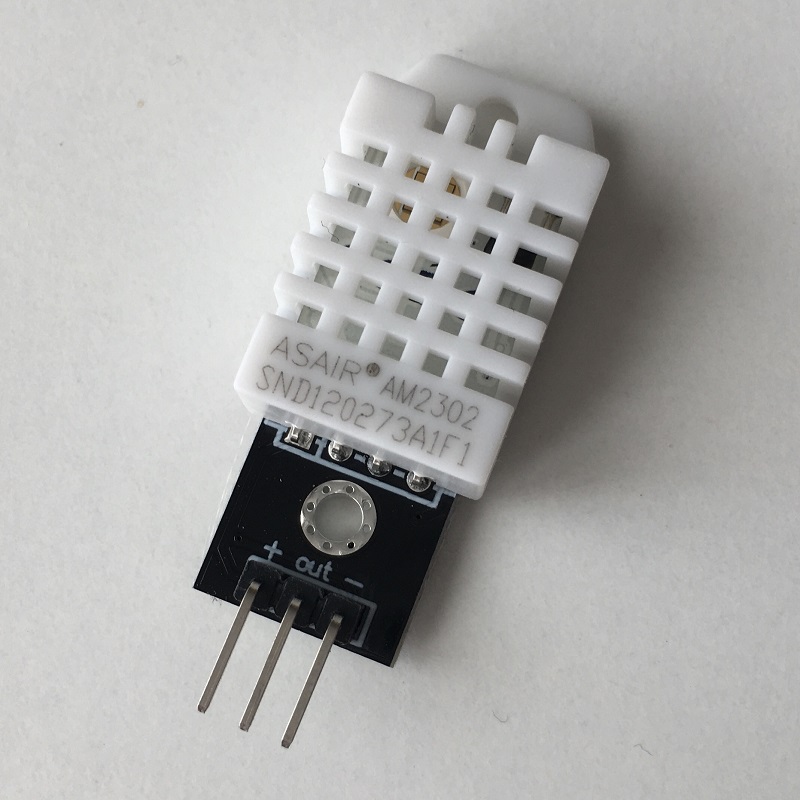
As we can see, it has three legs (by default, the sensor has four, one of them a Not Connected Pin without function). Let’s see each of them, from left to right in the image:
- VCC: power supply pin, marked with the «+» symbol.
- Datos: data output channel, marked as «out».
- GND: the ground one, marked with the «–» symbol.
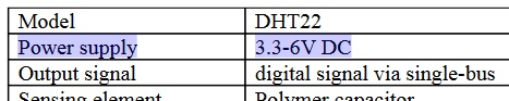
The next question to answer is: at how much power does the sensor work? Well, according to the documentation with its technical specifications, the sensor works between 3.3 and 6 volts.
Considering that the module we are going to work with, the ESP32-WROOM-32D, has both 3.3V and 5V power pins, we can use either one of them.
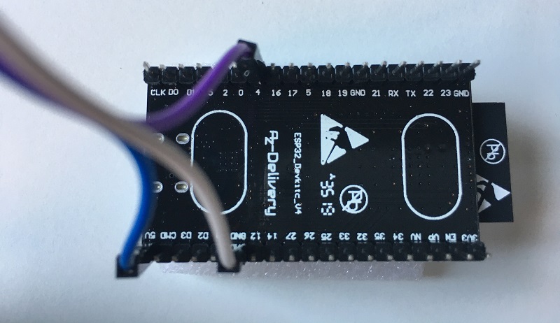
Let’s see the diagram of the module (this is the one I have, the DevKit V4):
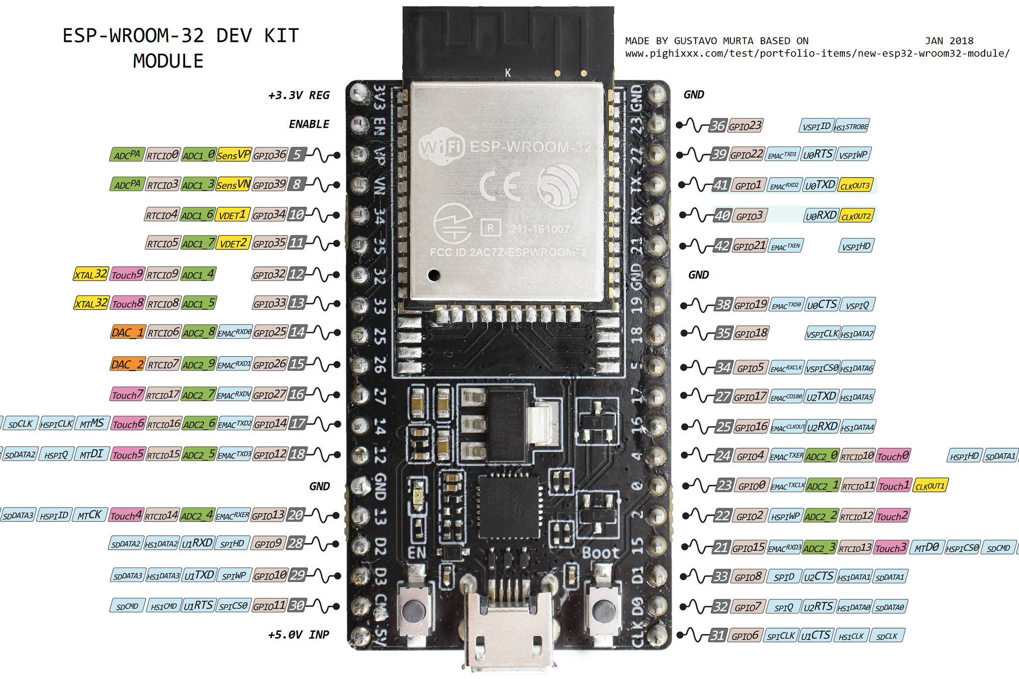
As you can see, we have two available power pins: the 3.3V pin, at the top left; and the 5V pin, at the bottom left. We have three grounding systems pins (marked as «GND»).
Both are valid. It all depends on how you are ultimately going to power the board. In my case I’m going to use the micro USB port as a power supply, meaning that the 5V pin will be available to feed the DHT22 sensor.
About the the data pin, many tutorials indicate that you are to connect it to the pin corresponding to the GPIO2. However, when loading the code in the WROOM module, if you are using the VCC pin (the 5V one) the compilation won’t work depending on the mode the board is in (we’ll talk about this later), so I have used the GPIO4 (which is two positions above the GPIO2).
Therefore the connections will be like this:
| DHT Module | ESP32-WROOM-32D Module | |
| Pin | + | 5V |
| Pin | out | GPIO4 |
| Pin | – | GND |
Next, we will connect the ESP32-WROOM-32D module to some computer through the micro USB port.
Preparing the development environment
If you are new to all this, the first thing I would tsuggest is to download the Arduino IDE (you can also do this online, but it’s better to use your own desktop).
Of course you can use other solutions like Visual Studio Code and its extensions (this one or this other one, for example), but to simplify things we will go the basic option. If you want to go VS, it’s your choice.
Once installed, if we tangle with the board selection options from the Tools > Board menu, we will see that the list of available boards does not include ours. It only has a few hundred Arduino board versions (that’s the thing about it…).
In order for our board to appear, we have to go to the IDE’s properties, under the File > Preferences menu, and at the bottom where it says something about «Additional Boards Manager URLs», include the following JSON:
https://dl.espressif.com/dl/package_esp32_index.json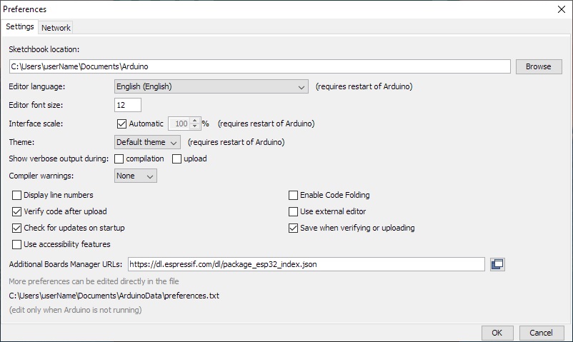
If you happen to already have another URL entered here, add a comma and then add the JSON.
Having done this, we go back to the Tools > Boards menu and select the «Boards Manager» option. In the window that will appear, we will have to say that we are looking for something called «esp32», which will filter the contents and the option that we want will appear.
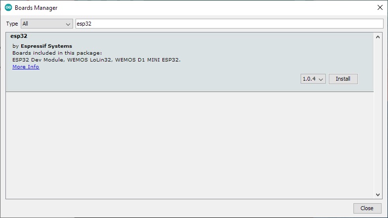
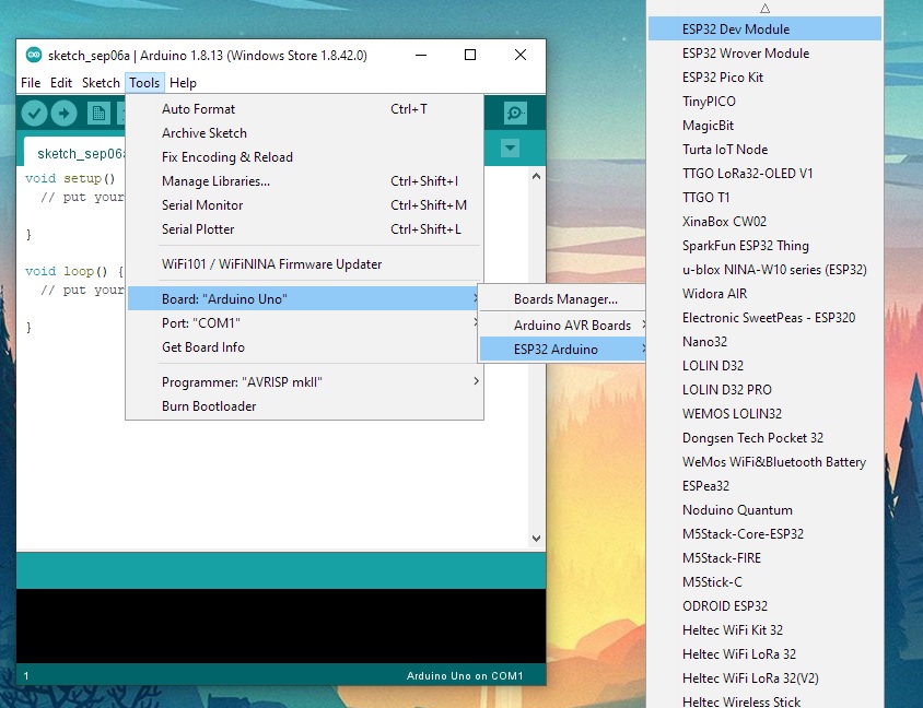
Now we install it and have patience, becuase it will take a while. When it’s done, we can choose our board from the Tools > Board menu, and there we will see a new drop-down menu called «ESP32 Arduino», where we can choose our board model. For the one I am using, that would be «ESP32 Dev Module».
Loading the libraries
Before we get on with it, all hands on deck, we must identify which libraries we will need – so that we install them and such.
As a sort of a quick list, we will need one for the temperature and humidity sensor, another one for the Wifi, another one to connect to an HTTP client, and another one to create JSON structures.
These libraries will be loaded into the IDE from the Sketch > Include Library menu, and once there we will select the «Manage Libraries…» option. A window, similar to the one with the boards, will appear. On that window we will have to find and install the following libraries:
- DHT sensor library (DHT.h)
- WiFi (WiFi.h; it should be installed by default)
- HttpClient (HTTPClient.h)
- ArduinoJson (ArduinoJson.h)
Note: you can always download the ZIP files from these libraries and install them manually.
OK, when all of this is ready, let’s get down to business!
Writing code
First, we will create a new project and save it with a name we will recognise. Having done this, we will load the libraries we are going to use.
// Load the necessary libraries
#include "DHT.h"
#include "WiFi.h"
#include "HTTPClient.h"
#include "ArduinoJson.h"
Next, we are going to define which type of DHT sensor we are going to use, and the GPIO that will receive the data. If you are secretly using a DHT11 or DHT12 sensor or module in this tutorial (which can be used, if you consider that legs are ordered differently), this is where you would specify that.
// Point the GPIO
#define DHTPIN 4

// Set the DHT sensor type between DHT11, DHT12 or DHT22
#define DHTTYPE DHT22

// Initialize the DHT sensor
DHT dht(DHTPIN, DHTTYPE);
With this, we would have already defined what the sensor is and we’re ready to request readings. Next we are going to configure the Wi-fi so we can escape from the board with it. Here we only have to specify which Wi-fi network we wish to connect to, and what its key is.
// Set the name and password of the Wifi network
const char* ssid = "NETWORK_NAME";
const char* password =  "NETWORK_PASSWORD";
It goes without saying that you must replace the «NETWORK_NAME» and «NETWORK_PASSWORD» in quotation marks with your network’s name and password. It goes without saying.
The next step will be to include the information to connect with the Platform; that is to say, we must specify the URL of the REST API service and the token (the alphanumeric long string) for identification.
// Set the Onesait Platform endpoint and the identification token
const char* opEndpoint = "https://lab.onesaitplatform.com/api-manager/server/api/v1/NAME_OF_YOUR_ENDPOINT_MINE_IS_arduinoDHT22Endpoint";
const char* opToken = "USER_TOKEN_SEE_PART_1_FOR_MORE_INFORMATION";
OK, the main part is already done. Now all that remains is to define a couple of properties, maybe three.
First of all, we have to decide how often we want to send data to the ontology. Remember, the sensor measures with a frequency of 2 seconds, but sending a data every two seconds is, we can say, a bit excessive. So let’s say a more convenient value, such as one minute (I mean, 60 seconds).
Then, if we remember the ontology scheme we created, one of the properties corresponded to the sensor’s ID, and another to its location. This is because we can be using more than one sensor (as it is the case), and so when filtering contents, this is useful for us. In order to be able to reuse the code in a simpler way, we define this here, so that it can be easily updated later.
Therefore, we will add these commented properties to the code:
// Set the device ID & location
const char* deviceId = "esp32-wroom-32D_01";
const char* deviceLocation = "Dinning Room";

// Set the waiting time between data reads in seconds
int readTime = 60000;
Well, that’s it for definitions, and now we go on to create the program’s configuration. Here we are going to configure the serial monitor to do the tests, connect to the Wi-fi and start reading the sensor data – because, if we do not connect to the network, what are we going to be measuring for? (I mean, since we are not going to do anything locally with that data).
As in previous cases, I have commented the code to explain a little bit what each thing is, because this often helps to understand the process.
void setup() {
  // Set the serial monitor channel to listen
  Serial.begin(9600);

  // Connect to the Wifi network
  WiFi.begin(ssid, password);

  // Wait until the WiFi connection is ready
  while (WiFi.status() != WL_CONNECTED) {
    delay(5000);
    Serial.println("Connecting to the WiFi network... please stand by.");
  }

  // Notify when it has been able to connect successfully
  Serial.println("Connected to the network.");
  Serial.println("IP address: ");
  Serial.println(WiFi.localIP());

  // Notify that the DHT22 sensor is initializing
  Serial.println("Starting DHT22 sensor reading...");

  // Start to read temperature and humidity
  dht.begin();
}Important: Sometimes the ESP32 module cannot connect to a defined Wi-fi network, or when it does connect, it then disconnects after some time (minutes, hours, etc.), all of which is related to the AUTH_FAIL error. This is a bit of a random mistake, and there are those who never see it, those who see it always, and others who see it sometimes. Still, it’s quite obvious that it’s a problem of the router you’re connecting to.
In my case, I have found a solution: Indicate a static IP when connecting to the Wi.fi network. If you want to do this, you will have to define under «const char* password», for example, these four new constants:
// Set the static IP address
IPAddress staticIP(192, 168, 1, 12);

// Set the router IP
IPAddress gateway(192, 168, 1, 1);

// Set the subnet IP
IPAddress subnet(255, 255, 255, 0);

// Use Google DNS
IPAddress dns(8, 8, 8, 8);
For the IP, specify the address you want. In my case, I have reserved a number of ports as static in the router, so I assigned #12 to the board that was giving me connection problem.
Then, and after the line «WiFi.begin(ssid, password)», add the following line:
// Configure the connection with custom IPs
WiFi.config(staticIP, gateway, subnet, dns);
Having done that, when we connect to the Wifi network, we will always connect to that IP.
Finally, we will define the code that will be continuously running on the board. I describe the meaning of each part of the code in the comments.
void loop() {
  // Time between reads
  delay(readTime);

  // Get the humidity
  float humidity = dht.readHumidity();
  // Get the temperature as Celsius (the default)
  float temperature = dht.readTemperature();
  // Get the temperature as Fahrenheit (isFahrenheit = true)
  float fahrenheit = dht.readTemperature(true);

  // Check if any reads failed and exit early (to try again).
  if (isnan(humidity) || isnan(temperature) || isnan(fahrenheit)) {
    Serial.println("Something has... failed while reading from the DHT sensor.");
    return;
  }


  // Check if the Wifi connection is working
  if(WiFi.status() == WL_CONNECTED) {
    // Notify the user
    Serial.println("Sending data...");

    // Make the connection to the API REST Endpoint on the Onesait Platform
    HTTPClient http;
    http.begin(opEndpoint);
    http.addHeader("Content-Type", "application/json");
    http.addHeader("X-OP-APIKey", opToken);

    // Create the JSON
    StaticJsonDocument<200> json;

    // Set the JSON properties
    JsonObject ontologyInstance = json.to<JsonObject>();
    JsonObject arduinoDHT22 = ontologyInstance.createNestedObject("arduinoDHT22");

    // Add the specific data to each JSON property
    arduinoDHT22["deviceId"] = deviceId;
    arduinoDHT22["location"] = deviceLocation;
    arduinoDHT22["temperature"] = temperature;
    arduinoDHT22["humidity"] = humidity;

    // Set a string to store the JSON serialized
    String string2send;

    // Serialize the JSON, and show it in the serial monitor
    serializeJson(ontologyInstance, string2send);
    Serial.println(string2send);

    // Post the JSON in the Endpoint
    int httpCode = http.POST(string2send);

    // Get the payload posted
    String payload = http.getString();

    // Show the returning code from the API REST and show what data has been uploaded in the ontology
    Serial.println("HTTP Return Code: ");
    Serial.println(httpCode);
    Serial.println("HTTP Response Body: ");
    Serial.println(payload);

    // Close the connection
    http.end();
  }
}
I have included the option to measure the temperature in Fahrenheit degreesin case any of you are interested in obtaining that data instead of using Celsius degrees (and because, in every tutorial out there, they show both data – it had to be said).
And that’s all, folks. With this code, we can recover the temperature and humidity data every minute, associate it to a JSON object that includes the sensor ID and its location, and send that JSON to the Platform to introduce the data in an ontology. When you explain it like that, it doesn’t sound so hard, does it?
Here’s the clean code (no comments or serials), in case you want to use it. I’ve commented the options to connect to a static IP. If you need that, uncomment the lines and specify a valid IP.
Remember also to change the name and password of the Wi-fi network, as well as the Endpoint‘s URL, the user token and your sensor’s ID and location – otherwise you will get the weirdest things later.
#include "DHT.h"
#include "WiFi.h"
#include "HTTPClient.h"
#include "ArduinoJson.h"

#define DHTPIN 4
#define DHTTYPE DHT22
DHT dht(DHTPIN, DHTTYPE);

const char* ssid = "NETWORK_NAME";
const char* password =  "NETWORK_PASSWORD";
//IPAddress staticIP(192, 168, XXX, YYY);
//IPAddress gateway(192, 168, 1, 1);
//IPAddress subnet(255, 255, 255, 0);
//IPAddress dns(8, 8, 8, 8);
const char* opEndpoint = "https://lab.onesaitplatform.com/api-manager/server/api/v1/NAME_OF_YOUR_ENDPOINT_MINE_IS_arduinoDHT22Endpoint";
const char* opToken = "USER_TOKEN_SEE_PART_1_FOR_MORE_INFORMATION";
const char* deviceId = "esp32-wroom-32D_01";
const char* deviceLocation = "Dinning Room";
int readTime = 60000;

void setup() {
  WiFi.begin(ssid, password);
  //WiFi.config(staticIP, gateway, subnet, dns);

  while (WiFi.status() != WL_CONNECTED) {
    delay(5000);
  }

  dht.begin();
}

void loop() {
  delay(readTime);

  float humidity = dht.readHumidity();
  float temperature = dht.readTemperature();
  float fahrenheit = dht.readTemperature(true);

  if (isnan(humidity) || isnan(temperature) || isnan(fahrenheit)) {
    return;
  }

  if(WiFi.status() == WL_CONNECTED) {
    HTTPClient http;
    http.begin(opEndpoint);
    http.addHeader("Content-Type", "application/json");
    http.addHeader("X-OP-APIKey", opToken);

    StaticJsonDocument<200> json;
    JsonObject ontologyInstance = json.to<JsonObject>();
    JsonObject arduinoDHT22 = ontologyInstance.createNestedObject("arduinoDHT22");

    arduinoDHT22["deviceId"] = deviceId;
    arduinoDHT22["location"] = deviceLocation;
    arduinoDHT22["temperature"] = temperature;
    arduinoDHT22["humidity"] = humidity;

    String string2send;
    serializeJson(ontologyInstance, string2send);

    int httpCode = http.POST(string2send);

    String payload = http.getString();

    http.end();
  }
}
Don’t go away, kids! We’ll be right back! We have the code ready, all right, but we still have to upload it to the board. Usually, with Arduino, this is as simple as clicking the arrow icon and presto!, but in the case of this board it’s not, because it has… several startup modes.
By default, if we try to upload code to the board, it won’t let us. To do this, you have to keep the «Boot» button pressed and then upload the code.
As this is a bit annoying, there is a combo to activate the default download mode, that allow us to upload the code directly:
- Press the «Boot» button and keep it pressed.
- Press the «EN» button.
- Release the «EN» button.
- Release the «Boot» button.
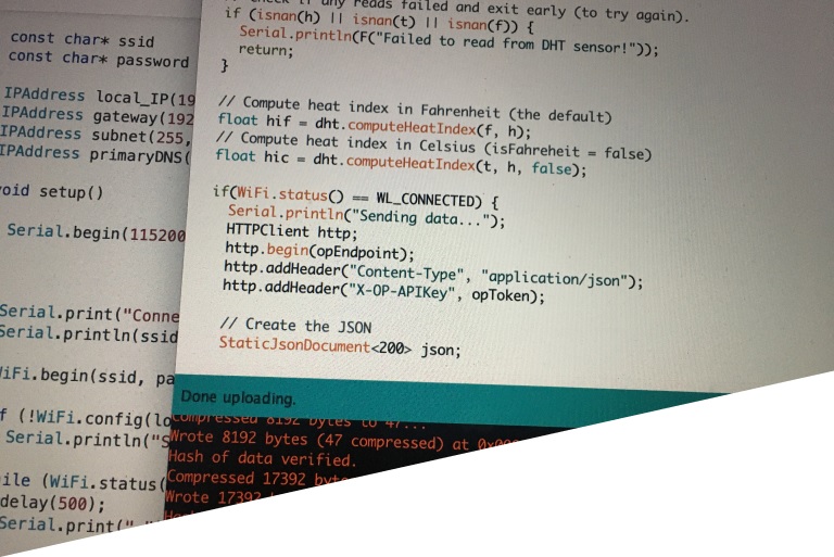
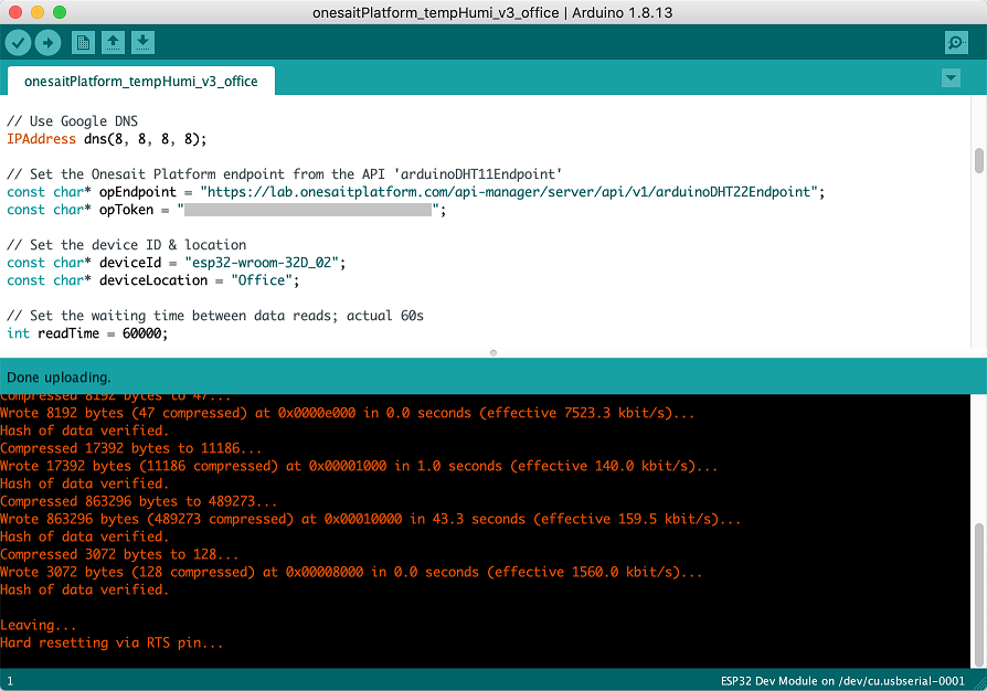
Whether you press and hold the button, do the combo or do nothing because there’s no need (that happened to me with one of the boards), we have uploaded the code to the board. If everything goes correctly, a final message similar to the one below should appear:
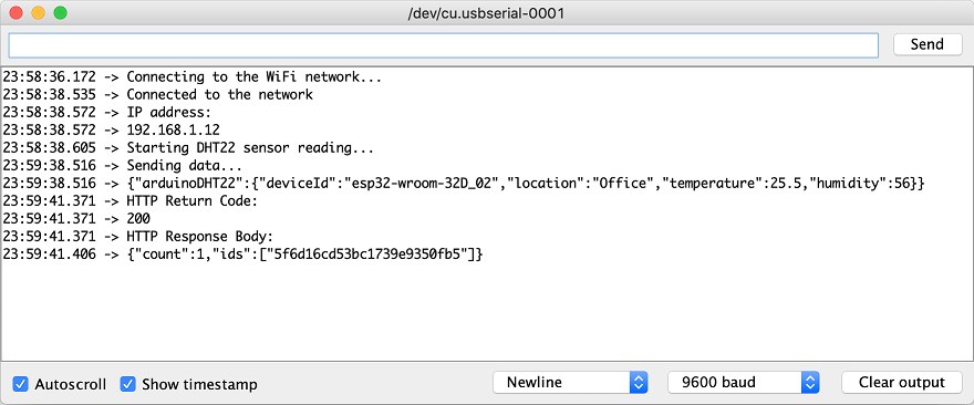
If you have loaded the code version with the serials, we can open the Serial Monitor, adjust the baud channel to whatever we have defined (9600 for the example) and see what outputs: First of all, a message should appear indicating that you are trying to connect to the Wi-fi network. If it succeeds at this, another message will appear specifying the IP with which you are connecting (which, if you have set it as static, should be the one defined above) and, after one minute of waiting for the loop, a message will appear indicating that the measurement is being carried out, along with the server’s response -which, if correct, will be 200- and the object that has been loaded into the ontology.
If we are using the clean code, or if we do not want to look at the monitor, we can go to the Platform and, in the menu Tools > Query tools, we will choose the ontology we are using to store the data (which in my case was arduinoDHT22) and make the following query:
SELECT * FROM arduinoDHT22 AS cIf, as we wish and hope, everything works as expected, the existing records in the ontology should appear; the first one should be the manual POST that we made from Swagger in the first entry, and all the following ones will be the ones that will arrive from our IoT gizmo:
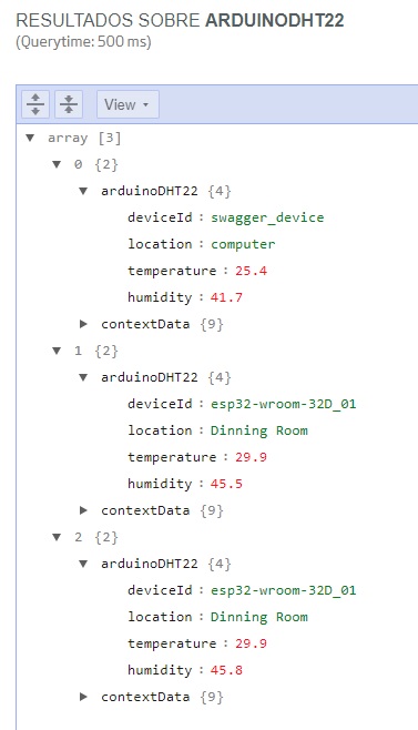
It turned out cool, right? Well, if we’ve reach this point, know that you already have an IoT sensor connected to the Platform, which receives data periodically, and you can interact with that data and do whatever you want.
To close up, I’d like to emphasize a detail: If we have a couple sensors working 24 hours a day for one year, measuring every minute, we are talking about 1,051,200 records per year, which is quite a figure.
So I would ask you that, if you are not going to need this data for a week or a month, it would be a good idea to clean up the ontologies about the dates before that limit. How can this be done? Let me tell you that FlowEngine is your friend: with a persistent process that deletes records prior to the date you indicate.
If you don’t know how to do that, we’ll explain you in some tutorial at some point… For now, I recommend you this DataFlow course that we have published in the blog. It can surely help you.
That’s all for now. I hope you have found it interesting and that you have succeeded in doing this. We are going to admit it, this is no piece of cake.
In our next entry, we will see how to generate a Gadget that shows us the temperature and humidity information in real time (that is to say, every minute) in the Dashboard, and the Datasource that’s going to feed it.


Pingback: IoT for around the house: Connecting a sensor with the Onesait Platform (part III) – Onesait Platform Blog
Pingback: Creating Ontologies from Time Series – Onesait Platform Blog
Pingback: Creating Ontologies from Time Series – Onesait Platform Community